This section contains short notes on the following topics:
MBGP (Multicast Border Gateway Protocol), an extension of BGP, is a mechanism for the propagation of multicast routing information amongst different AS’ (Autonomous Systems). Thus, just like what BGP does in the case of unicast routing, MBGP provides information about the reachability of various multicast networks and implements policy control for multicast routing. MBGP peers, the routers exchanging multicast routing information via MBGP, populate their local routing tables, referred to as MBGP-tables, using the route updates that they get from their neighbors. Each entry in an MBGP table corresponds to a route to a network and the networks are represented in CIDR notation, i.e. a 4-octet net-number followed by the net-mask A route is represented using two fields. One of the fields is the IP address of the next hop router and the other, called AS path, is a sequence of AS’ that the packets have to hop through to reach the destination-network. The later field, AS path, is what most of our work on MBGP topology has been based on. MBGP routes, like BGP routes, are the shortest path from the router to a network. The
basic difference between BGP and MBGP lies in the manner in which these routes are used.
For unicast routing BGP routes are used to decide the interface on which the packets are
to be forwarded to. On the contrary, for multicast routing MBGP routes are used to perform
the RPF check, i.e. to decide the interfaces on which the packets are *not* to be
forwarded. If a router receives a packet destined for a multicast group on an interface,
it does a look up on the MBGP table to check if the interface that the packet was received
from also leads to the shortest path to the source of the packet. If the check succeeds,
the packet is forwarded on the other interfaces. The packet is discarded otherwise. Affects of Glitches in MBGP on the Multicast Routing: The MBGP infrastructure of the multicast Internet does not always work as expected. The flaws creep in because of two primary reasons: (1) misconfigured MBGP peers and (2) hardware failure, that is the failure of the physical links and/or devices like switches, routers etc. Such flaws directly affect the accuracy of the route advertisement process amongst the MBGP peers. The glitches in route advertising may result into classic network problems like isolated network clusters and routing blackholes. As mentioned earlier, MBGP routes are used to perform the RPF check. If route to a
network is not available to a router or is wrong, the RPF check for the incoming packets
might fail. Consequently, though a router might be getting packets destined to a group
from a source, it might not forward them to the downstream routers/hosts. Significance of the MBGP Topology: MBGP has lately emerged as a major interdomain routing protocol for multicast. The
fact, that the stability and the optimality of MBGP topology directly affects the proper
functioning of the multicast infrastructure, has made efficient monitoring of this
topology very important. In several respects, MBGP topology delineates the actual topology
of the Multicast Internet and it can be described as a view of the main topology presented
at a very coarse granularity. Each the networks in a routers MBGP table represent a set of
host(s) that are reachable from that router. Unlike unicast the availability of an MBGP
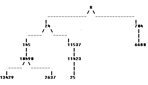
route to a network does not Deriving Topology Information from a Router's MBGP-State: Each entry in a router’s MBGP table contains an AS path from the router to a multicast network. Ideally, at any point of time, a router must have at least one AS path to each of the existing multicast networks and, hence, must be capable to determine route to any host on the Multicast-Internet. Based on the above fact it can be inferred that if all the AS paths present in a MBGP table are aggregated the resulting mesh would be the AS topology of the entire multicast Internet. As an AS path is the sequence of AS’ that the packets hops through from the router to the destination network, each pair of consecutive AS’ in an AS path represent a *unidirectional* link. Aggregation of AS paths simply means joining these links into a mesh. The mesh thus generated represents the router’s view of the topology-tree of the multicast Internet. Router is the root, AS’ are the intermediate nodes and the multicast networks are the leaves of this topology-tree. The important point to note is that all the edges point away from the router, that is the root. A simple example of the generation of the topological tree by AS-path aggregation is given below Consider a router R, with MBGP entries for only 4 networks: The topology generated by the aggregation of above AS paths will be the following: Displaying the Topology (Introduction to Otter): All the topology maps presented on these pages have been drawn using CAIDA’s general purpose network visualization tool, Otter. Otter is a Java-based, interactive topological visualization tool for visualizing arbitrary network data that can be expressed as a set of nodes, links or paths. In case of Mantra, the topology views presented at this site, the information about the links and nodes is extracted from the router’s MBGP tables. Some of the really cool features of Otter include its efficiency in drawing sensible topology maps and its ability to color code the links and/or nodes on the basis of different values. These features have been used extensively in the different views of topology presented on these pages. More information on the color-coding that we have used can be found on the pages for different topology views.go top
|


